After the failure and lessons learned with the design and production of Lou1:d I didn’t give up. And started working on Lou1:e.
I decided to skip the extra column of switches to the left, my idea was that I could keep the wirings and add solder points for an external 5 row 1 column PCB if I wanted (spoiler: i didn’t do it). Also I wanted to use more common key switches so I created a new footprint that allows for both MX and Choc v1 and v2 key switches. It also has a cutout for reverse mount RGB LED, so I can get that extra bit of advantage in Fortnite.
So I started a new project in EasyEDA and got to work. Since I decided to skip the extra column, and the gap between, I had to find a new place for the MCU and the larger components. The 2U high enter was kept, and the offset of 1/2U made room for the components needed. But the routing was not as fun as with Lou1:d.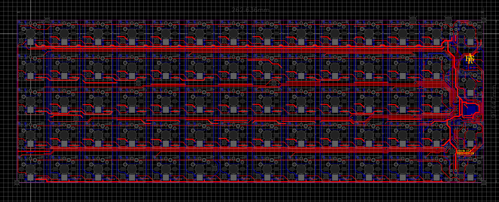
There was a lot of tracks that had to go from the right most part of the PCB and out to the rest, and that I wanted RGB LED didn’t exactly give me any extra space. But after a couple weeks of tweaking and sometimes starting over I was satisfied.
Instead of a USB connection on the PCB I wanted more freedom in the design of the case and opted to just be able to either solder the cable directly or add a daughterboard with USB-C on and place it somewhere nice in the case.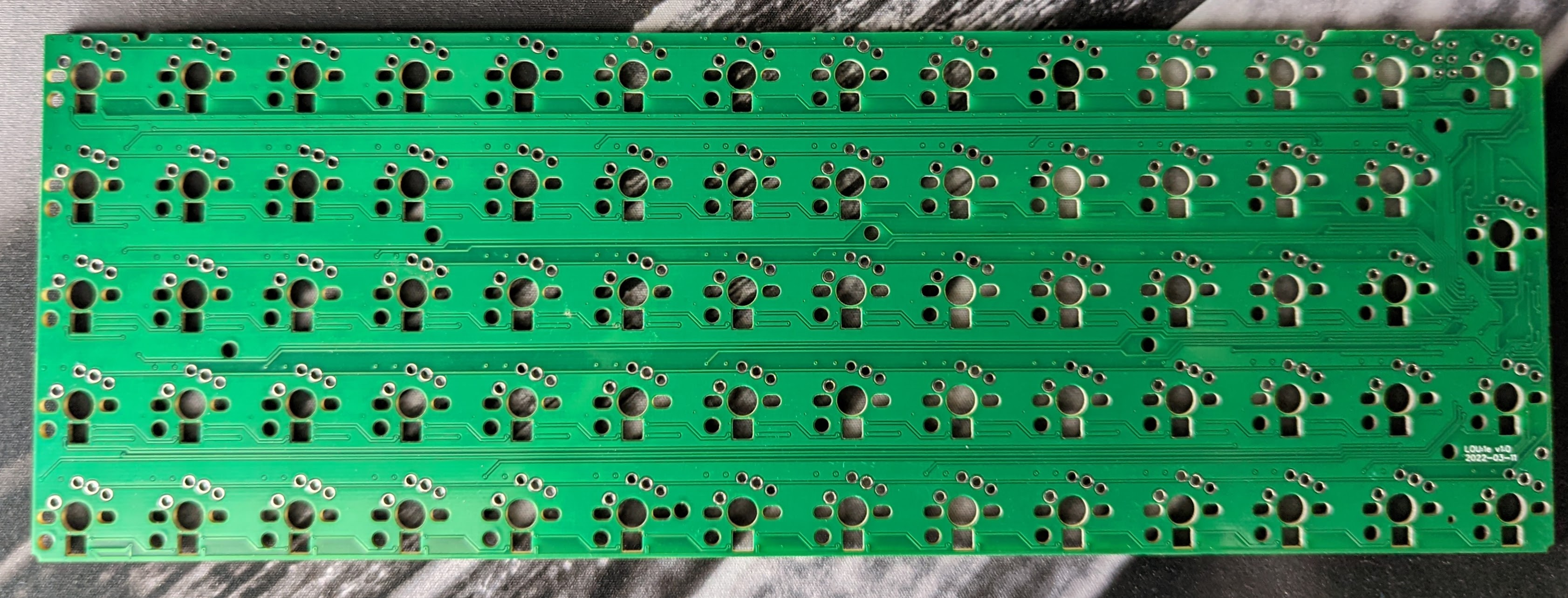
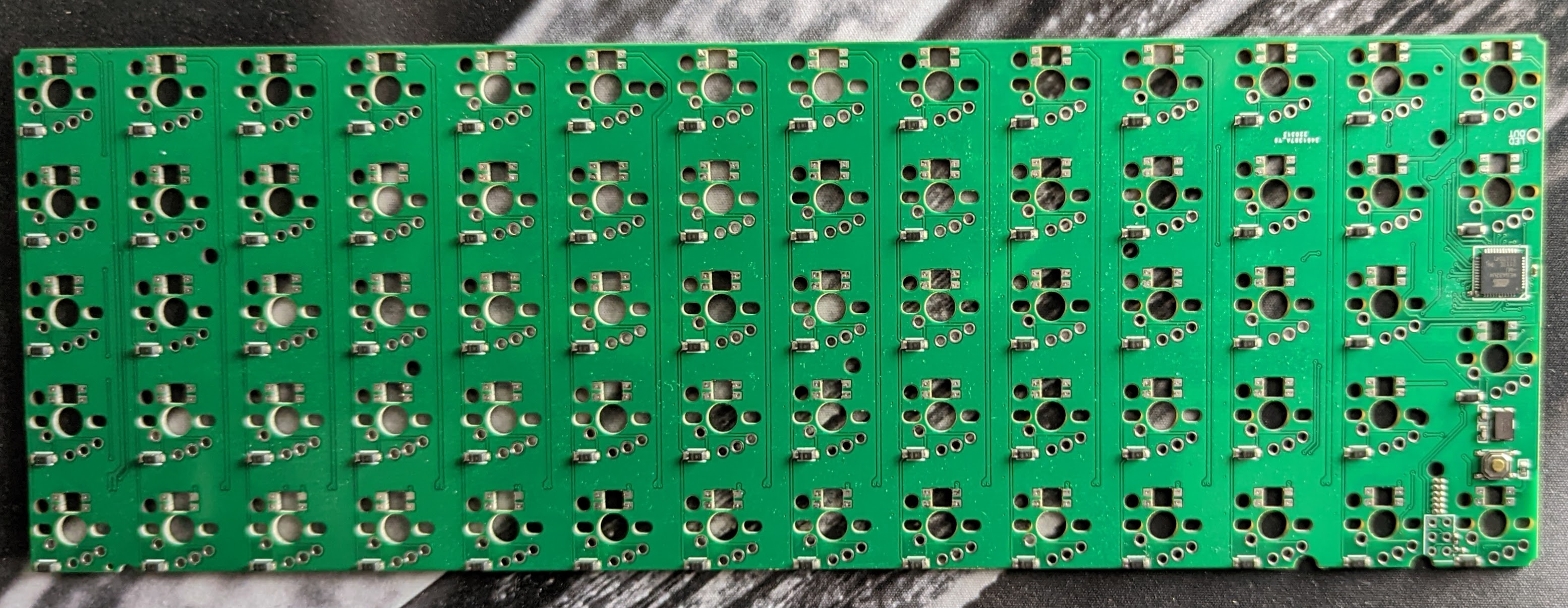
I used the same MCU as in Lou1:d, the Atmega 32U4, and componentwise most of the PCB was identical to the predecessor, with the exception that the components was on the correct side. Even if I copied almost all components from Lou1:d there was a couple of errors. The main problem was that I forgot two resistors for the USB data-lines but it wasn’t harder than getting two PTH resistors with correct values and solder them in line with the USB cable.
For this layout I also created top-plates, made them as PCBs for ease and let JLCPCB produce these too. I also got sheets of cork laser cut by Cotter and placed them between the PCB and the top plate.
I did forget to make cutouts for the stabilizers and had to do it by hand, but it wasn’t hard with a sharp knife and some bloodshed.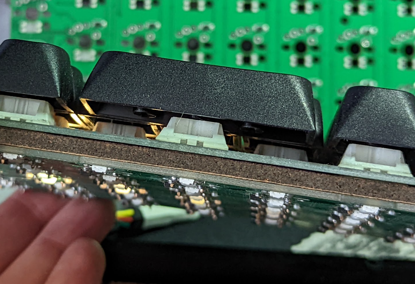
With this PCB I’ve built two keyboards that I use as daily drivers. One at home and one at work. For both I use Boba U4 Silent switches. You can read about the first one here.